|
|
Step 9-13 : Building the Hardware
Step 11 - Fully integrated. :
Site is being updated however please start here for these esp8266 builds.
We will describe the second GPS version here, this can be used as a standalone device that a pilot can carry to just broadcast their position aswell but with the kobo attached its a full flight computer, it can be also configured back to a Wifi version if required.
We have found the Kobo wifi to be ok, it can disconnect itself sometimes and then take a while to reconnect, or you can reconnect manually, the hard wired version doesnt suffer from any of these disconnections and works 24/7.
Please log into the Air-ware webpage and switch the connection mode to hardwired to use this version.
The only other item you will need is a switch for turning the Airware on and off, we could do this with a transistor but for ease of use and the ability to use the kobo as just a ereader or set your flight computer up with no current drain from the system it is advisable. 20 of them here
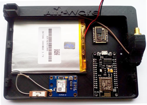
We usually just use some double sided tape to attach the Nodemcu, RF module and GPS to the inside of the case, we added a 5000mah battery inside the unit, this gives around 20+ hours runtime so plenty for a days flying !
We have made 2 different cases, a small aerial case (quarter wave) and a larger aerial case ( half wave ), they are both here on thingiverse to download and print, alternatively contact us for a printed one, quarter wave and the half wave.
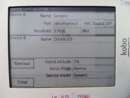
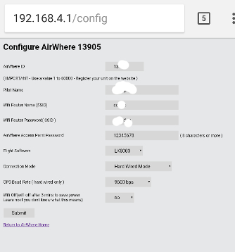
Data from the GPS is passed to the Nodemcu, processed and sent on to the Kobo.
The "Integrated Version" Baud rate between Kobo and Nodemcu is 57600.
However the Baud and serial port settings between GPS and Nodemcu depends on the design of the GPS board you choose to use, typically 9600, /dev/ttymxc0 , 8bit.
NB. This latter 9600 setting is made via the Configuration option of the webpage.
Confusingly therefore, the GPS baud rate and the Kobo baud rate are different and therefore they need setting independently, as shown in the above pictures.
We are now running a voltage regulator HT7333 between the battery and lora/nodecmu boards - this is to get a 3.3v direct to the chips, helps with lora reception - details coming shortly
**********IMPORTANT*********
Please read the following page and go through the instructions step by step and make sure each step is working perfectly before proceding with the build,
if you dont follow these steps it will make it extremely difficult to find out whats wrong later if you have any issues.
>>>>>PLEASE READ - Building diagnostic page - PLEASE READ! <<<<<<
**********IMPORTANT*********
Also please read these notes :-
Notes
Half Wave - larger antenna - Download
Quarter Wave - smaller antenna - Download
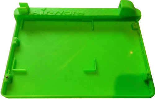
Or contact us for a prebuilt one, this case creates a very neat self contained unit with the larger battery.
Wiring diagram is similar to the previous module with a battery and a switch incorporated, the battery is charged by just plugging the kobo in as normal.
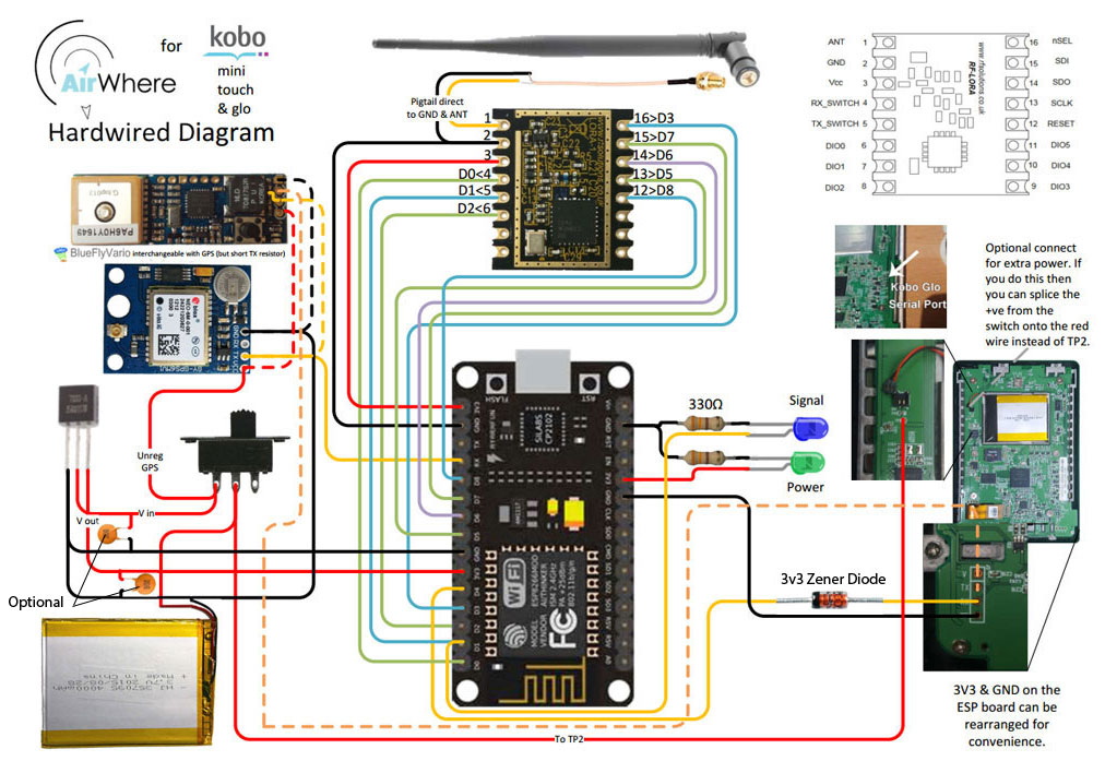
The following pinouts can be also used.
| Nodemcu | RF LORA | Aerial | Power LED | Transmission LED | GPS | Kobo |
| D0 | 4 | | | | | |
| D1 | 5 | | | +ve | | |
| D2 | 6 | | | | | |
| D3 | 16 | | | | | |
| D5 | 13 | | | | | |
| D6 | 14 | | | | | |
| D7 | 15 | | | | | |
| D8 | 12 | | | | | |
| RX | | | | | TX | |
| 3V | 3 | | +ve | | +VE/VCC | +ve |
| GND | 2 | Outer | -ve | -ve | -ve | GND/-VE |
| 1 | Inner | | | | |
| D4 | | | | | | RX |
PLEASE MAKE SURE YOUR GPS HAS A FIX FOR TESTING!
(easy thing to miss when testing and you think your wiring is wrong and its not ! )
The Zener diode is optional, this is to solve a problem when the airware system and gps is turned on before the Kobo. Its advisable to use this as without it in place you have to turn the kobo on before the Airware otherwise a circuit is made within the Kobo itself and the Node gets power by the D4 pin and gets quite upset.
Please make sure you have 3volt GPS, if you have a 5volt you can attach it to Vin instead of 3v, this will power it, check the GPS manual for details.
If you are going to add an external battery, something we highly recommend for £8 then just attach the postive and negative to the ground on the kobo, you can use one of the wide headed bolts as a ground aswell, and then the positive can be soldered to the small pad near the power supply, its called TP2 on the printed circuit board, nice of them to add that for us ! ;) Check the diagram for details. Battery can be found here on ebay.
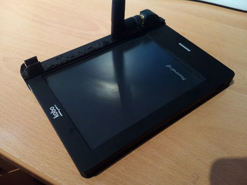
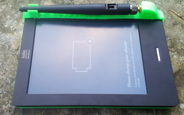
If you want to run a BlueFly Vario - please check this page :- BlueFly vario
|
|
|
|
|
|

